|
XinChang JIAYANG Bearings Co.,Ltd.
|
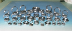
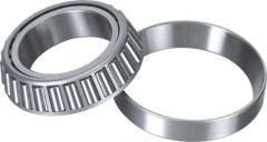
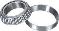
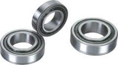
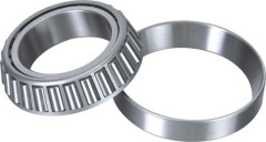
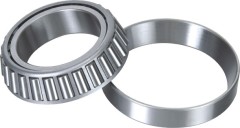
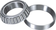
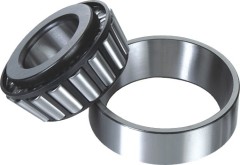
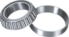
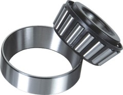
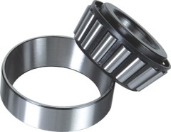
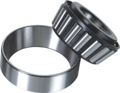
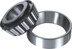
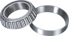
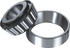
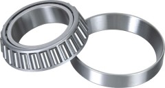
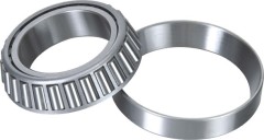
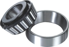
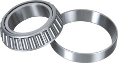
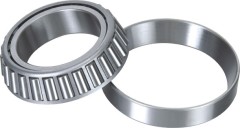
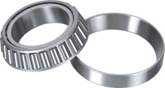
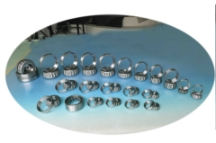
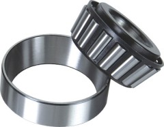
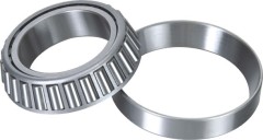
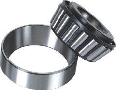
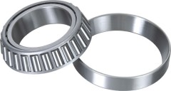
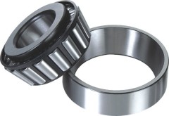
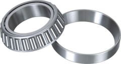
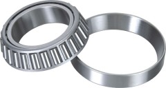
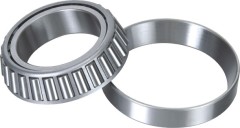
Automobile Inch Size Taper Rolling Bearing
| Payment Terms: | T/T,L/C |
| Place of Origin: | Zhejiang, China (Mainland) |
|
|
|
| Add to My Favorites | |
| HiSupplier Escrow |
Product Detail
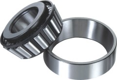
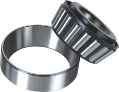
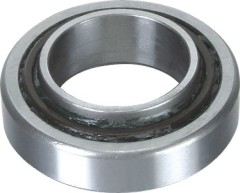
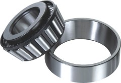
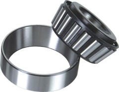
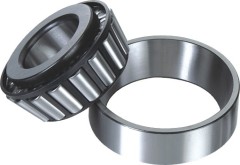
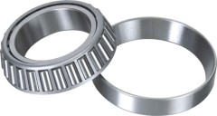
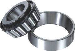
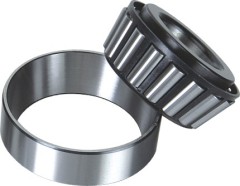
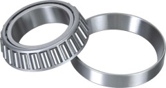
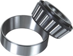
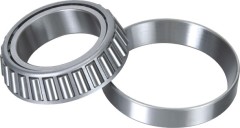
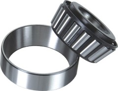
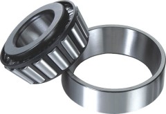
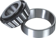
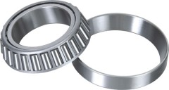
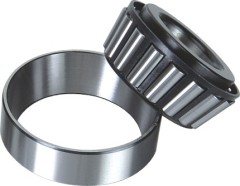
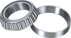
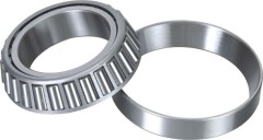
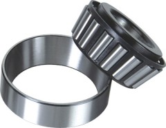
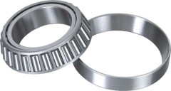
Tapered roller bearings (inch series)
Tapered roller bearings(inch series)


Bearing No. | (mm) Dimensions | (Kg) | Load Ratings (KN) | ( rpm ) Limiting speed | ||||||||
d | D | T | B | C | Rmin | rmin | Weight | Cr | Cor | Grease | Oil | |
M88043/M88010 | 30.162 | 68.262 | 22.225 | 22.225 | 17.462 | 2.3 | 1.5 | 0.399 | 55.8 | 70.5 | 5600 | 7500 |
Description
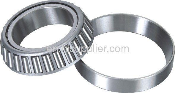
The inner and outer ring raceways are segments of cones and the rollers are also made with a taper so that the conical surfaces of the raceways and the roller axes if projected, would all meet at a common point on the main axis of the bearing.
This conical geometry is used as it gives a larger contact patch, which permits greater loads to be carried than with spherical (ball) bearings, while the geometry means that the tangential speeds of the surfaces of each of the rollers are the same as their raceways along the whole length of the contact patch and no differential scrubbing occurs. When a roller slides rather than rolls, it can generate wear at the roller-to-race interface, i.e. the differences in surface speeds creates a scrubbing action. Wear will degenerate the close tolerances normally held in the bearing and can lead to other problems. Much closer to pure rolling can be achieved in a tapered roller bearing and this avoids rapid wear.
The rollers are guided by a flange on the inner ring. This stops the rollers from sliding out at high speed due to their momentum.
The larger the half angles of these cones the larger the axial force that the bearing can sustain.
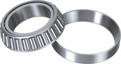
Tapered roller bearings are separable and have the following components: outer ring, inner ring, and roller assembly (containing the rollers and a cage). The non-separable inner ring and roller assembly is called the cone, and the outer ring is called the cup. Internal clearance is established during mounting by the axial position of the cone relative to the cup.
Metric tapered roller bearings follow the designation system defined by ISO 355.
History
In 1898, Henry Timken was awarded a patent[1] for the tapered roller bearing. At the time, Timken was a carriage-maker in St. Louis and held three patents for carriage springs. However, it was his patent for tapered roller bearings that allowed his company to become successful.
Tapered roller bearings were a breakthrough at the end of the 19th century because bearings used in wheel axles had not changed much since ancient times. They relied on bearings enclosed in a case that held lubricants. These were called journal bearings and depended on lubricants to function. Without proper lubrication[2], these bearings would fail due to excessive heat caused by friction. Timken was able to significantly reduce the friction on his bearings by using a cup and cone design incorporating tapered bearings which actually rolled, which reduced the load placed on the bearings by distributing the weight and load evenly across the cups, cones, and bearings.
Applications
In many applications tapered roller bearings are used in back-to-back pairs so that axial forces can be supported equally in either direction.
Pairs of tapered roller bearings are used in car and vehicle wheel bearings where they must cope simultaneously with large vertical (radial) and horizontal (axial) forces. Applications for tapered roller bearings are commonly used for moderate speed, heavy duty applications where durability is required. Common real world applications are in agriculture, construction and mining equipment, axle systems, gear box, engine motors and reducers.
Didn't find what you're looking for?
Post Buying Lead or contact
HiSupplier Customer Service Center
for help!
Related Search
Inch Taper
Taper Bearing
Large Size Bearing
Inch Taper Roller Bearings
Rolling Bearing
Taper Roller Bearing
More>>


